 github
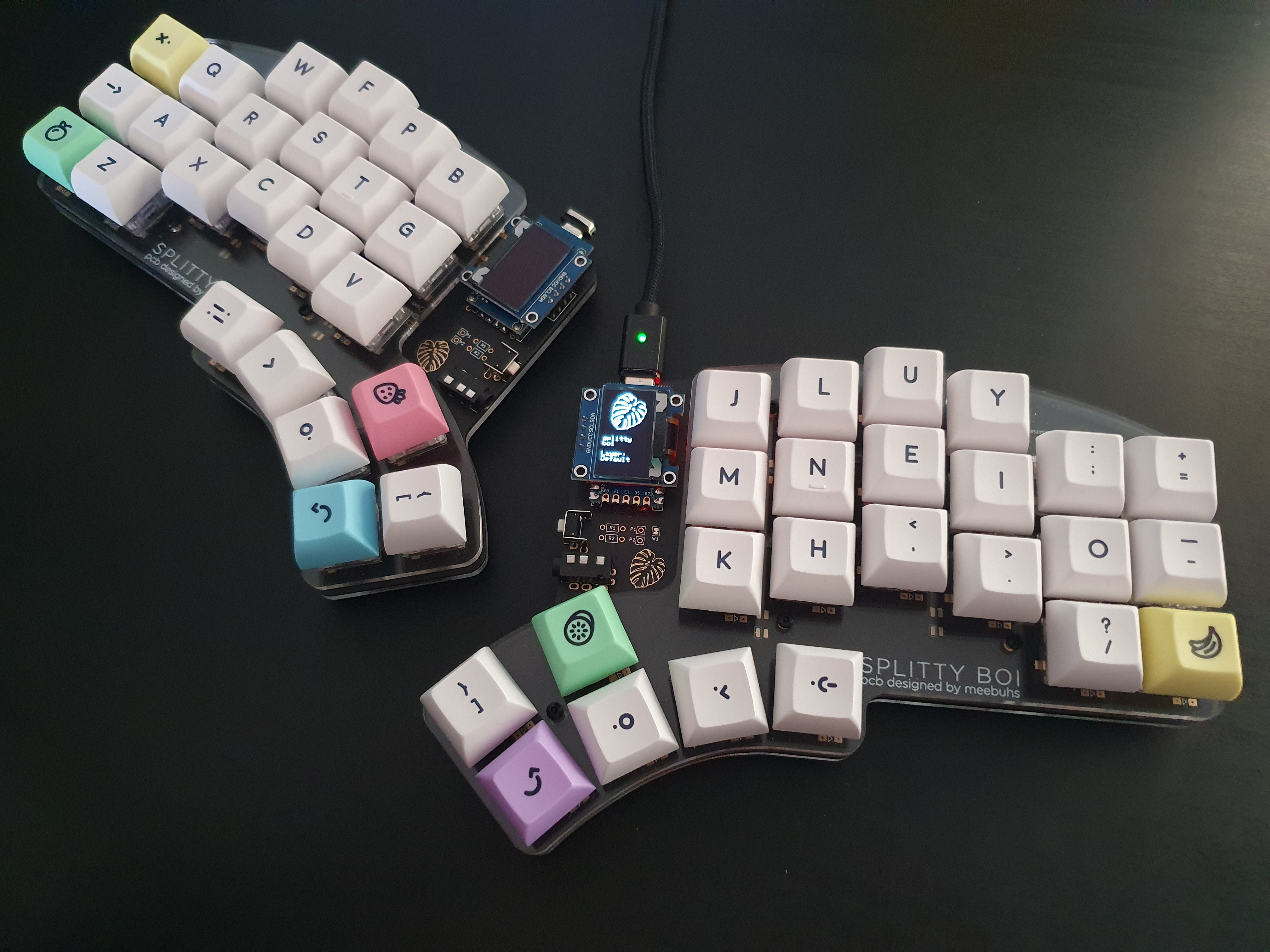
Splitty Boi
Given the amount of my time I spend using my keyboard, whether it’s writing code, playing games, chatting with friends or otherwise bouncing around the internet, the idea of a more ergonomic keyboard was appealing. I purchased a Lily58 Pro kit to assemble and after about a month of it being stuck in the US, I was getting impatient and decided it would be more fun to design my own keyboard anyway. So I did.
The Lily58
The Lily58 is a fairly popular split keyboard among the ergomech community however for many of you, this post is likely its introduction. Like many other split keyboards (including the helix which it is based on) the Lily58 uses QMK firmware running on a pair of Pro Micros. One Pro Micro acts as the master, connected to the pc via usb and running the firmware, while the other is the slave, reporting its key presses to the master via a TRRS cable. It also has support for a 128x32 OLED screen on each side which by default is used to display the logo, layer state and keypress information. The Pro variant of the Lily58 features support for Kailh hotswap sockets which remove the need to solder the switches to the keyboard and allows them to be easily interchanged.
There are three changes of my own that I wanted to make to the Lily58 Pro.
- I wanted RGB LED underglow and per key backlighting utilising SK6812MINI LEDs.
- I wanted to use bigger 128x64 OLED screens.
- I wanted a columnar stagger and thumb key arc that was designed to fit my hands.
The Corne
The Corne is another popular split keyboard with very similar origins to the Lily58. It is very similar except that it doesn’t have a number row and features the RGB lighting that I wanted. I wasn’t sure if I wanted a number row or not and I don’t think there is a way to know without trying it.
I decided to test it by removing the number row from my current keyboard and putting them on a layer. If I decided I didh’t need a number row by the time the pcb design was done, I could remove it.
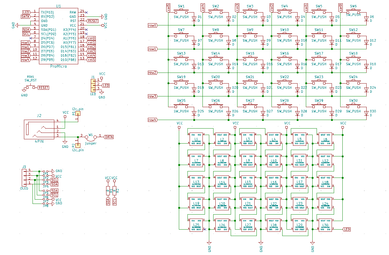
Iterating
The first step was to set up the schematic. Using the Lily58 as a starting point, I added an extra switch to the bottom row of the matrix as an extra thumb key and I added the LED matrix.
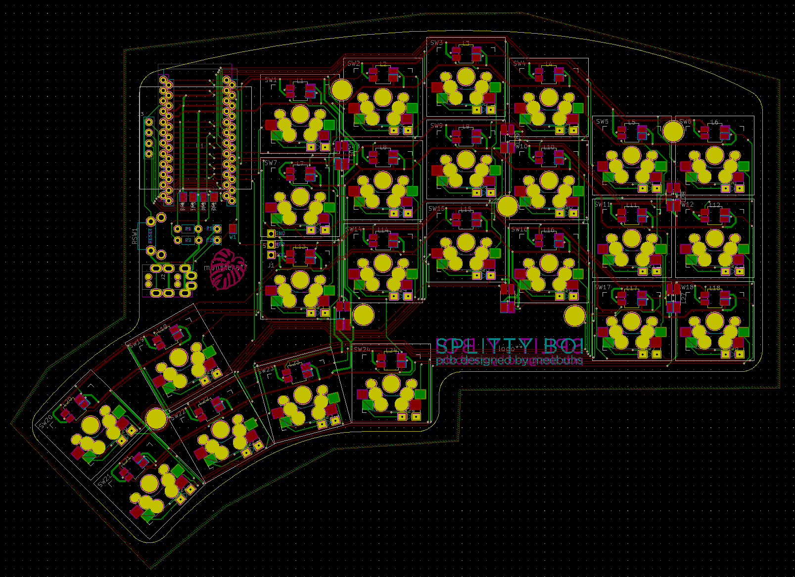
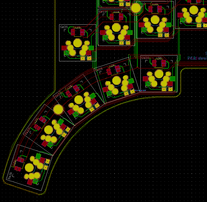
Then began the fun of routing the traces on the PCB.
Rev 0.4
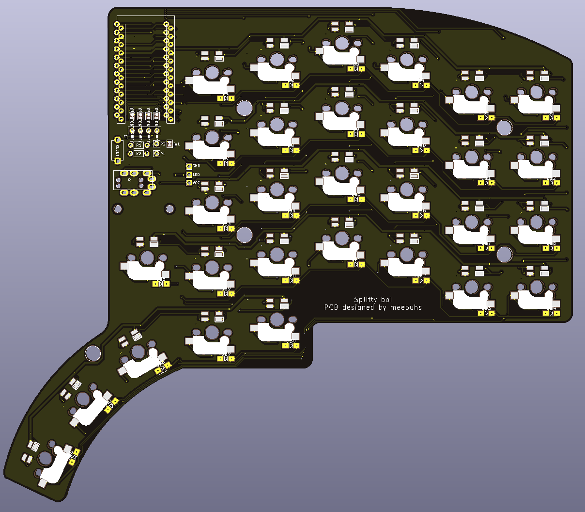
This is a 3D render of the first completed revision of the splitty boi pcb. Comparing it to the Lily58 Pro, I had:
- added the per key backlighting.
- rearranged the TRRS jack and reset switch to take up less space.
- arranged the three inner-most thumb keys in an arc.
- altered the columnar stagger to be more aggressive.
I made a quick note to change the silkscreen for the hotswap sockets and I kept adjusting.
Rev 0.6
I wasn’t entirely satisfied with the columnar stagger and the thumb key placement, especially the two outer keys which matched the stagger of the columns. I plotted the key placements and started taking measurements for where I felt everything should be.
The result of my experimentation here was that I moved the thumb cluster down and inward toward the hand, allowing the thumb and fingers to remain relaxed while on the home row. I also adjusted the staggers, bringing the pinky columns further down as well as moving the extra key below the Pro Micro down to be hit by the thumb instead of the index.
At this point I was happy with the stagger of each column but I hadn’t yet added the underglow that I wanted, nor had I adjusted for the larger OLED. I also felt like the inner most thumb key was slightly too far away (you can see my hand flatten as I stretch to reach it in the gif above).
Also on the list, was removing the number row. I had decided by this point that I was comfortable with the numbers on a layer and actually enjoyed having my parentheses on my home row.
Rev 1.0
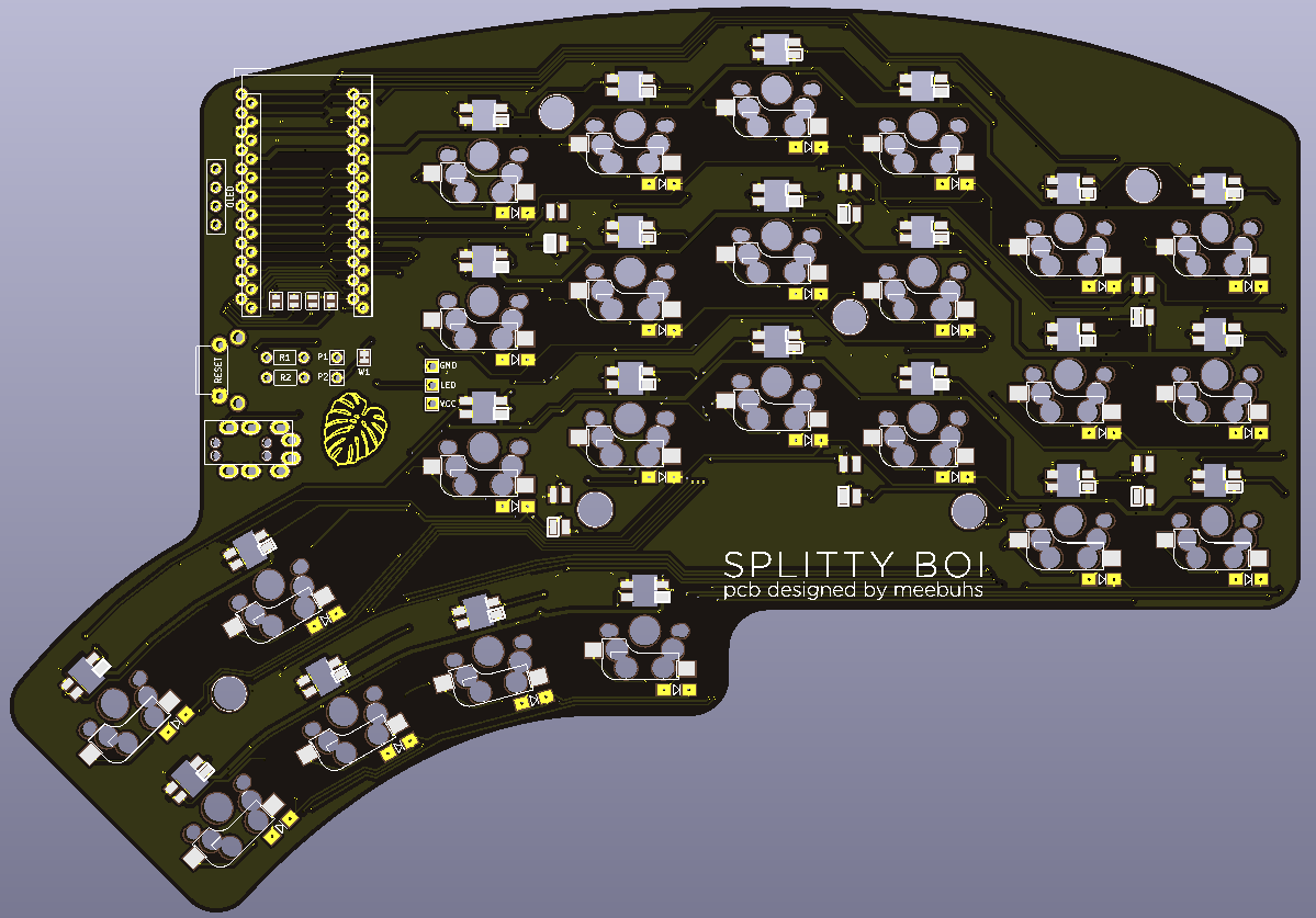
The final revision incorporates the changes mentioned above as well as a couple others.
- The number row was removed.
- The surface mount underglow LEDs were added.
- The inner-most thumb key was moved into a second row of the thumb arc so that it could be reached more easily.
- The OLED connection was rotated to accomodate the larger screen in portrait.
- The monstera leaf graphic was added and the silkscreen updated.
Assembly
I had the PCBs manufactured by JLCPCB, the top and bottom plates laser cut by Ponoko and ordered the components from Aliexpress and Digikey. I am still waiting on the LEDs however I will post a full build guide once I have them installed.